Audison APBX 10AS2 - Bedienungsanleitung - Seite 14
43
Owner’s Manual
9
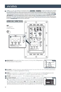
PWR-PROT:
Status led. Power on (blue colour) - Protection mode (red colour): the amplifier will automatically shut-
down when overheating - over/under power supply voltage occur.
/
Led di segnalazione di stato. Amplificatore in
funzione (led blu)- Amplificatore in protezione (led rosso): l’amplificatore si spegnerà automaticamente in caso
di surriscaldamento - sovra/sotto alimentazione.
HI-LEVEL INPUT:
HI-level inputs for speaker signals, Left and Right channels. If the source does not
feature pre-amplified outputs, connect to the HI-level speaker outputs (0.2÷8 VRMS). Left & Right signals
are summed into the amplifier to obtain a mono signal for the subwoofer
/
Ingressi ad alto livello
canali Sinistro e Destro. Collegare le uscite ad alto livello amplificate per gli altoparlanti (0.2÷8 VRMS),
provenienti dalla sorgente audio, se questa non dispone di uscite preamplificate. I segnali L e R sono
sommati nell’ampli per ottenere un segnale mono per il subwoofer.
8
7
REMOTE CONTROL PORT:
Input for REMOTE SUB VOLUME CONTROL. Connect the sub volume control HRC
AP supplied
/
Ingresso per il REGOLATORE DEL VOLUME DEL SUBWOOFER. Collegare qui il regolatore HRC
AP incluso nella confezione.
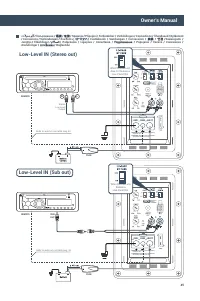
LOW-LEVEL INPUT:
Left and Right pre-amplified input channels. Connect to pre-amplified audio source
unit output. Gain adjustment: 0.1÷4 VRMS. Left & Right signals are summed into the amplifier to obtain
a mono signal for the subwoofer.
/
Ingressi preamplificati canali Sinistro e Destro. Connettere alle uscite
preamplificate della sorgente. Guadagno d’ingresso regolabile: 0.1÷4 VRMS. I segnali L e R sono sommati
nell’ampli per ottenere un segnale mono per il subwoofer.
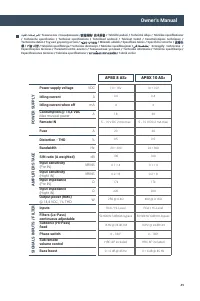
10
FUSE:
20 A blade type protection fuse for APBX 8 AS
2
( 30 A for APBX 10 AS
2
)
/
Fusibile di protezione tipo
autolama da 20 A per APBX 8 AS
2
(30 A per APBX 10 AS
2
).
12
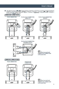
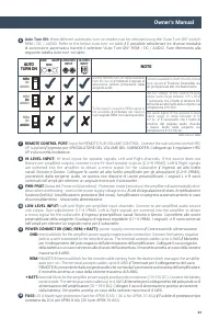
AUTO
TURN ON
LOW LEVEL
INPUT
HI-LEVEL
INPUT
NOTE
Use the Remote turn-on signal available
from the source
/
Utilizzare il segnale di
accensione remoto proveniente dalla
sorgente audio.
Function available for both HI and LO level
input signals
/
Funzione
Disponibile sia
per gli ingressi ad alto che basso livello.
To be used in case the REM signal is
not available
/
Utilizzare nel caso in
cui il segnale REM non sia disponibile.
The DC voltage of the source HI-level
output needs range between 2÷5 V DC
/
È necessario che il livello di tensione DC
dell’uscita ad alto livello della sorgente sia
compreso tra 2÷5 V DC.
The audio signal of the source LO-level
output needs to range between 4÷10
mV AC.
/
È necessario che il livello di
tensione del segnale audio d’uscita
a basso livello della sorgente sia
compreso tra 4÷10 mV AC.
AUDIO
DC
REM
AUDIO
DC
REM
AUDIO
DC
REM
Auto turn on table
GND
REM
+BATT
POWER CONNECTOR (GND; REM; + BATT):
power supply connections
/
Connessioni di alimentazione.
GND:
terminal block for the amplifier power supply negative pole connection. Connect the battery negative
pole or a wire connected to the vehicle chassis. The terminal accepts cables up to 4 AWG
/
Morsetto
per il collegamento del polo negativo dell’alimentazione dell’amplificatore. Collegare il cavo negativo
della batteria o un cavo connesso allo chassis dell’autovettura. Il morsetto accetta un cavo della sezione
massima di 4 AWG.
REM:
REMOTE IN terminal block for the remote cable coming from the device which manages the amplifier
auto turn-on. The terminal accepts cables up to 8 AWG
/
Terminale per il collegamento del cavo
REMOTE IN, proveniente dalla sorgente audio che comanda l’accensione automatica dell’amplificatore.
Il morsetto accetta un cavo della sezione massima di 8 AWG.
+ BATT:
terminal block for the amplifier power supply positive pole connection (10÷16V DC). Connect the battery
positive pole. The terminal accepts cables up to 4 AWG
/
Morsetto per il collegamento del polo positivo di
alimentazione dell’amplificatore (10 ÷ 16 V DC). Collegare il cavo di alimentazione positivo proveniente
dalla batteria. Il morsetto accetta un cavo della sezione massima di 4 AWG.
11
Auto Turn ON:
three different automatic turn-on modes can be selected using the “Auto Turn ON” switch:
REM / DC / AUDIO. Refer to the below Auto turn-on table
/
È possibile selezionare tre diverse modalità
di accensione automatica tramite il selettore “Auto Turn ON”: REM / DC / AUDIO. Fare riferimento alla
seguente tabella Auto turn-on table.
6
„Anleitung wird geladen“ bedeutet, dass Sie warten müssen, bis die Datei vollständig geladen ist und Sie sie online lesen können. Einige Anleitungen sind sehr groß, und die Zeit, bis sie angezeigt wird, hängt von Ihrer Internetgeschwindigkeit ab.